Insulation and Sheath Thickness on the Small Sizes
The published dimension table gives 0.7 mm of insulation and 0.8 mm of sheath for every size from 1.5 mm² to 10 mm², a constant 1.5 mm of compound per side across a band where the copper area changes by a factor of about 6.7. On these sizes the wall thickness is a fixed design choice, and the diameter grows because of the conductor inside it.
Key takeaways
- Insulation is published at 0.7 mm and sheath at 0.8 mm from 1.5 mm² through 10 mm²; larger sizes step up to 0.9 mm to 1.7 mm insulation and 0.8 mm to 1.7 mm sheath.
- Both layers are electron-beam cross-linked XLPO in low-smoke halogen-free compound.
- Overall diameter across that band moves from 4.6 mm to 7.5 mm, while weight per metre moves from 34 g/m to 130 g/m.
- A 10 kV spark test during production and a 6.5 kV AC five-minute test on the finished cable are the published electrical checks on those walls.
Why one wall thickness covers five sizes
The table lists a single insulation thickness and a single sheath thickness for the 1.5, 2.5, 4, 6 and 10 mm² entries, then changes the rule for the sizes above them. Read across the band, the copper area grows from 1.5 mm² to 10 mm² while the compound around it does not change at all, so the wall is not being sized to the conductor area. That is worth knowing when a specification treats "the insulation" as one number for a whole installation: on this family the number is 0.7 mm on a rooftop string and something else entirely on a 240 mm² feeder. The practical effect is that the small sizes stay slim and light no matter which one is chosen, and the incremental cost of moving from 4 mm² to 6 mm² shows up in the conductor rather than in the jacket around it.
The published figures, size by size
Nominal overall diameter is given as 4.6 mm at 1.5 mm², 5.0 mm at 2.5 mm², 5.5 mm at 4 mm², 6.0 mm at 6 mm² and 7.5 mm at 10 mm². Nominal weight for the same five sizes is 34, 45, 59, 78 and 130 g/m. The conductor behind the wall changes construction at 4 mm²: 39 strands of 0.25 mm at 1.5 mm² and 49 at 2.5 mm², then 56, 84 and 142 strands of 0.29 mm from 4 mm² upward. The 1500 V product page states that the insulation and the sheath are both electron-beam cross-linked XLPO in low-smoke halogen-free compound, and that the finished cable is supplied in black or red. A buyer comparing quotes on the small sizes will find that KUKA CABLE publishes those three lines, diameter, weight and compound, and that they are the part of the data sheet which differs between suppliers.
What the walls are asked to withstand
Two production figures describe the electrical job. A spark test at 10 kV runs during manufacture, and the finished cable is given 6.5 kV AC at 50 Hz for five minutes. The first looks for pinholes and thin spots as the cable passes down the line; the second confirms the completed length. The mechanical and environmental duty comes on top of that: water resistance, UV accelerated weathering, abrasion, cold bending and tensile testing after ageing all appear in the manufacturer's test list. The 2,000-hour xenon lamp programme, which the site equates with about 360 weathering cycles, is arranged on finished cable precisely because the sheath is the layer that meets sunlight, humidity and ozone first, and the elongation reserve published for the compound, up to 185% against a requirement of more than 125%, is what stops that outer wall from cracking as it ages. The temperature window for the same construction is −40 °C to +90 °C.
Reading thickness together with diameter
The site pairs every size with a minimum bending radius of four times the outer diameter, so the wall and the conductor together set the practical limit on how tightly the cable can be routed. Across the small band the rule does not move much, because the diameters move from 4.6 mm to 7.5 mm; the change that matters to an installer is that a 10 mm² cable needs noticeably more room at a corner than a 4 mm² one, even though both carry the same 0.7 mm and 0.8 mm walls. Where space is tight, the published dimensions suggest choosing on the route and the current rather than on the jacket, since the jacket is the same either way. Where the route is long, the bending rule stops being the constraint and the current-carrying area starts to be.
| Cross-section | Insulation | Sheath | Overall diameter | Weight per metre |
|---|---|---|---|---|
| 1.5 mm² | 0.7 mm | 0.8 mm | 4.6 mm | 34 g/m |
| 2.5 mm² | 0.7 mm | 0.8 mm | 5.0 mm | 45 g/m |
| 4 mm² | 0.7 mm | 0.8 mm | 5.5 mm | 59 g/m |
| 6 mm² | 0.7 mm | 0.8 mm | 6.0 mm | 78 g/m |
| 10 mm² | 0.7 mm | 0.8 mm | 7.5 mm | 130 g/m |
| 16 mm² | 0.9 mm and above | 0.8 mm and above | 8.8 mm | 190 g/m |
Where the diameter comes from
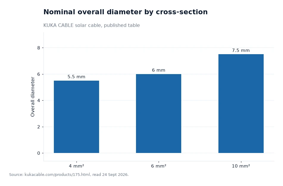
The chart below shows nominal overall diameter for the three sizes the site calls commonly used, and it is the clearest way to see that the wall is not what drives growth. From 4 mm² to 10 mm² the diameter rises by 2 mm while insulation and sheath stay at 0.7 mm and 0.8 mm; the extra diameter is conductor area and the stranding that fills it. A designer who needs a slimmer profile therefore has room to move downward in size without losing wall thickness, whereas a designer who needs more current has to accept the larger outside dimension as part of the bargain. Both readings come from the same published table, which is the point of publishing it.
Worked example: how much of the diameter is copper
Take the 6 mm² entry. It is built from 84 strands of 0.29 mm, so the published strand count and strand diameter give an illustrative copper area of about 5.55 mm² (author's calculation: 84 × π × (0.29 ÷ 2)² = 5.55, assuming the strands pack densely with no gaps). A circle of that area has a radius of about 1.33 mm, while the published overall diameter of 6.0 mm gives a radius of 3.0 mm, so roughly 1.67 mm per side is available for everything that is not copper. The published insulation and sheath together account for 1.5 mm of that, and the small difference is the space between strands. The arithmetic is the author's, the dimensions and the strand data are the manufacturer's, and the conclusion is simply that about half the radius on a small solar cable is compound rather than metal.
Frequently asked questions
How thick are the insulation and sheath on the small sizes?
Both figures are published as 0.7 mm of insulation and 0.8 mm of sheath for every size from 1.5 mm² to 10 mm², in electron-beam cross-linked XLPO that is low-smoke and halogen-free in both layers. Above 10 mm² the site gives 0.9 mm to 1.7 mm insulation and 0.8 mm to 1.7 mm sheath instead.
Does a thicker wall mean a thicker cable?
Not across the small band. Insulation and sheath stay at 0.7 mm and 0.8 mm while overall diameter rises from 4.6 mm to 7.5 mm, so the extra diameter comes from the conductor area and its stranding rather than from additional compound.
What to check on the datasheet
Check that the insulation and sheath are both quoted as cross-linked XLPO rather than one cross-linked layer over a thermoplastic one, since the published construction uses the same compound in both. Check the two wall figures separately, 0.7 mm and 0.8 mm on the small sizes, and confirm which band the ordered size falls into if the project also uses 16 mm² or larger. Ask for the spark test voltage and the five-minute test voltage on the finished cable, because those are the published checks that a wall of this thickness is being measured against. Finally, confirm the colour and the conductor stranding, because both appear on the same data sheet, and check the certificate names published for the line, which include TUV, IEC, CE, SAA, CPR and UL on the certificates page. The site publishes no price, minimum order or lead time, so those items belong in the quotation rather than the technical comparison.
Insulation and sheath thicknesses of 0.7 mm and 0.8 mm, with the diameters beside them, are quoted from the manufacturer's own website, kukacable.com, noted 24 Sept 2026[1].